
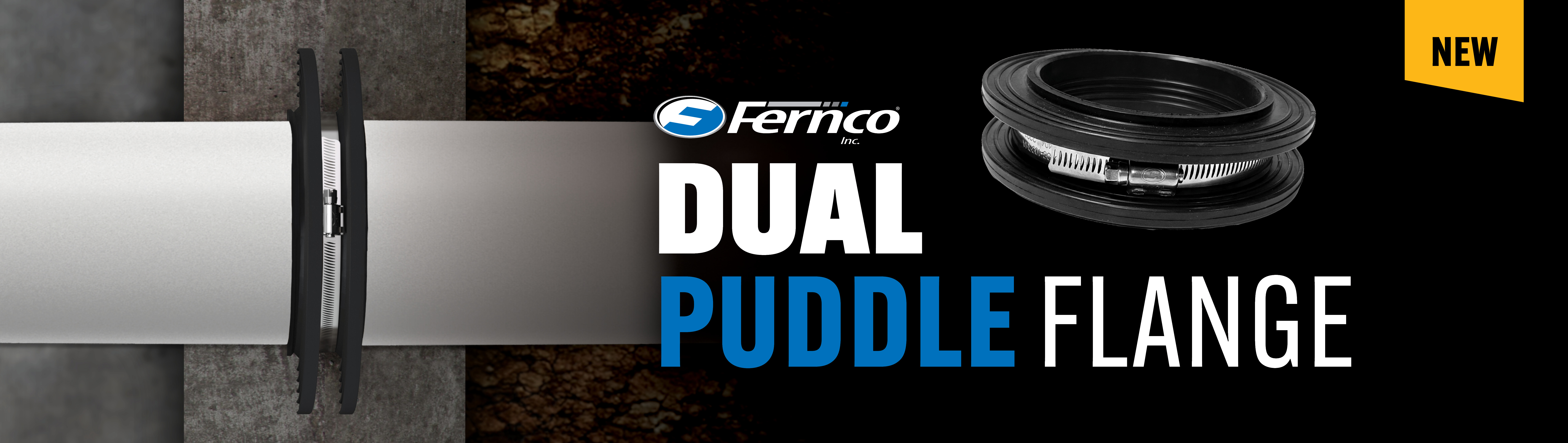

DualPuddle Flange
Seal pipe penetrations before the pour. An EPDM body with two flanges is clamped around the pipe and cast into the concrete wall or slab. It closes the gap that opens as concrete cures and shrinks away from the pipe, so it has to be on the pipe before the concrete is placed.
Where 5.65″ comes from: the flange is 1.65″ wide along the pipe (nominal, Fernco part drawing), and Fernco’s installation notes call for at least 2″ of concrete on every surface of the flange. 1.65″ + 2″ + 2″ = 5.65″ minimum wall or slab thickness at the flange. Cutaway view.
Concrete shrinks away from the pipe. The flange closes the gap.
When a pipe is cast into concrete, a leak path forms as the concrete dries and shrinks away from the pipe surface. The Dual Puddle Flange is a barrier across that path.
- Clamped to the pipe. A stainless steel clamp holds the rubber body against the pipe.
- Coated by the concrete. Wet concrete coats the flange’s large surface area during the pour.
- Follows the shrinkage. As the concrete cures and shrinks, the flange compresses and then relaxes to fill gaps.
- Blocks infiltration and exfiltration. A barrier to water, gases and hydrocarbons.
Seal radon entry paths at pipe penetrations.
The EPA notes that radon can move up from the ground into buildings through openings in floors or walls in contact with the ground. The gap around a pipe through the foundation is one of those openings. Cast in around the pipe, the Dual Puddle Flange blocks gas moving along the outside of the pipe through the concrete.
It addresses that one entry path. Joints, cracks, sumps and the rest of a radon control system still need their own details.
Horizontal through walls. Vertical through slabs.


- Foundation walls and basements
- Floor slabs
- Tanks
- Manhole chambers and shafts
- Pools
- Plastic
- HDPE
- Steel
- Cast iron
- Concrete. A cement mortar wash can be used to seal the pipe surface.
Find your size by pipe outside diameter.
Measure the pipe OD where the flange will sit and choose the part whose range covers it. DPF25–DPF375 are stocked. DPF400–DPF630 are special order.
| Part | Min. pipe OD | Max. pipe OD | Flange OD | Typical pipe | Availability |
|---|---|---|---|---|---|
| Stocked | |||||
| DPF25 | 0.59″ | 1.00″ | 2.95″ | ½″ IPS | Stocked |
| DPF32 | 1.01″ | 1.38″ | 3.23″ | ¾″ IPS · 1″ IPS | Stocked |
| DPF40 | 1.39″ | 1.75″ | 3.54″ | 1‑¼″ IPS | Stocked |
| DPF50 | 1.76″ | 2.20″ | 3.94″ | 1‑½″ IPS · 1‑½″ no‑hub | Stocked |
| DPF63 | 2.24″ | 2.70″ | 4.45″ | 2″ IPS · 2″ no‑hub | Stocked |
| DPF75 | 2.75″ | 3.35″ | 4.92″ | 2‑½″ IPS · 3″ no‑hub* | Stocked |
| DPF90 | 3.38″ | 3.99″ | 5.63″ | 3″ IPS | Stocked |
| DPF110 | 4.00″ | 4.52″ | 6.30″ | 4″ IPS* · 4″ SDR 35 · 4″ no‑hub | Stocked |
| DPF125 | 4.75″ | 5.29″ | 6.89″ | – | Stocked |
| DPF140 | 5.30″ | 5.99″ | 7.48″ | 5″ IPS · 5″ no‑hub* | Stocked |
| DPF160 | 6.00″ | 6.74″ | 8.27″ | 6″ IPS · 6″ SDR 35 · 6″ no‑hub | Stocked |
| DPF175 | 6.75″ | 7.50″ | 8.86″ | – | Stocked |
| DPF200 | 7.51″ | 8.40″ | 9.84″ | 8″ SDR 35* · 8″ no‑hub* | Stocked |
| DPF225 | 8.41″ | 9.35″ | 10.83″ | 8″ IPS | Stocked |
| DPF250 | 9.36″ | 10.25″ | 11.81″ | – | Stocked |
| DPF275 | 10.26″ | 11.25″ | 12.80″ | 10″ IPS · 10″ SDR 35 · 10″ no‑hub | Stocked |
| DPF315 | 11.26″ | 12.75″ | 13.78″ | 12″ IPS* · 12″ SDR 35 · 12″ no‑hub | Stocked |
| DPF325 | 12.76″ | 13.50″ | 14.76″ | – | Stocked |
| DPF350 | 13.51″ | 14.35″ | 15.75″ | 14″ IPS | Stocked |
| DPF375 | 14.36″ | 15.30″ | 16.73″ | 15″ SDR 35* | Stocked |
| Special order | |||||
| DPF400 | 15.39″ | 16.34″ | 17.72″ | 16″ IPS · 15″ no‑hub | Special order |
| DPF425 | 16.38″ | 17.32″ | 18.70″ | – | Special order |
| DPF450 | 17.36″ | 18.32″ | 19.69″ | 18″ IPS | Special order |
| DPF475 | 18.35″ | 19.29″ | 20.67″ | – | Special order |
| DPF500 | 19.33″ | 20.28″ | 21.65″ | 20″ IPS | Special order |
| DPF525 | 20.31″ | 21.26″ | 22.64″ | – | Special order |
| DPF550 | 21.30″ | 22.24″ | 23.62″ | – | Special order |
| DPF575 | 22.28″ | 23.23″ | 24.61″ | – | Special order |
| DPF600 | 23.27″ | 24.21″ | 25.59″ | 24″ IPS | Special order |
| DPF630 | 24.25″ | 25.20″ | 26.57″ | – | Special order |
Ranges and flange OD from the Fernco part drawing. Typical pipe uses standard published ODs: IPS covers Schedule 40 PVC, steel and IPS HDPE; SDR 35 is PVC sewer pipe; no-hub is cast iron soil pipe. * Standard OD is within 0.02″ of the range limit, so manufacturing tolerance can put the actual pipe in the next range. Always measure the actual pipe. For pipe outside these ranges, contact Fernco.
Four steps before the pour.
- Prep the pipeClean the pipe where the flange will sit and remove visible scratch marks. On concrete pipe, a cement mortar wash can be used to seal the surface.
- Fit the flange to the pipeStretch the flange over the pipe and push it into position. Soap and water helps. In some cases the seal’s inside diameter is smaller than the pipe OD, and removing the clamp can make stretching easier.
- Tighten the clampIf you removed the clamp, refit it. Torque the stainless steel clamp to 60 in-lb.
- Check the coverMake sure the flange will have at least 2″ of concrete on every surface, then pour.
| Concrete cover | 2″ minimum on every surface of the flange |
| Thickness at the flange | 5.65″ minimum (1.65″ flange + 2″ cover each side) |
| Concrete | Waterproof concrete should be used |
| Clamp torque | 60 in-lb |
| Pipe support | Fully supported to withstand the pour. The flange provides no axial restraint |
| Axial load | Do not use where the pipe is subject to axial loading |
Specifications.
| Body | EPDM rubber, two flanges |
| Clamp | 300-series stainless steel worm gear |
| Flange width | 1.65″ along the pipe (nominal) |
| Flange OD | About 2″ larger than the pipe, depending on size (see size table) |
| Temperature | −60°F to 180°F constant, 212°F intermittent |
| Barrier | Water, gases including radon, and hydrocarbons |
| Direction | Infiltration and exfiltration |
| Orientation | Horizontal and vertical |
| Sizes | 30 parts covering pipe OD from 0.59″ to 25.20″ (see size table) |
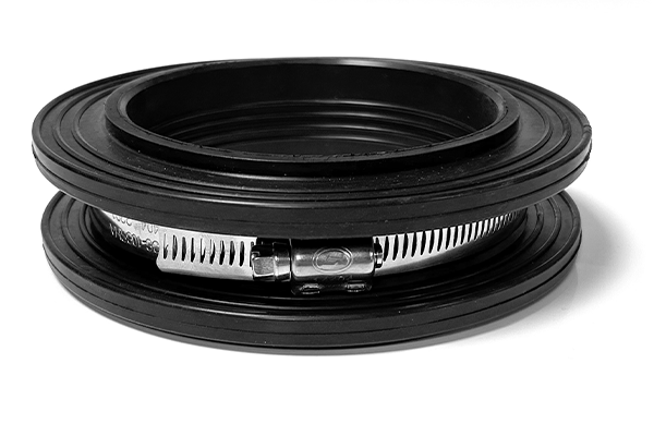
PIPE PENETRATION WATERSTOPS (PUDDLE FLANGES)
[Edit bracketed items to suit the project.]
PART 2 - PRODUCTS
2.1 PIPE PENETRATION WATERSTOPS
A. Basis of design: Fernco, Inc., Davison, Michigan. Dual Puddle Flange, DPF series.
B. Description: Cast-in elastomeric waterstop with two flanges, clamped around the pipe and embedded in the concrete wall or slab, to block water, gases including radon, and hydrocarbons from moving along the outside of the pipe.
C. Materials:
1. Body: EPDM rubber.
2. Clamp: 300-series stainless steel worm-gear clamp.
D. Service temperature: -60 deg F to 180 deg F constant; 212 deg F intermittent.
E. Size: Select by measured pipe outside diameter, within the manufacturer's published fit range.
PART 3 - EXECUTION
3.1 INSTALLATION
A. Install in accordance with the manufacturer's written instructions, before concrete placement.
B. Clean the pipe surface where the flange will be fitted and remove visible scratch marks. [On concrete pipe, a cement mortar wash may be used to seal the surface.]
C. Fit the flange over the pipe and position it [at the location indicated on the drawings]. Soap and water may be used as a lubricant.
D. Refit the clamp if removed for fitting. Tighten the clamp to 60 in-lb.
E. Support the pipe fully to withstand concrete placement. The flange provides no axial restraint. Do not use where the pipe is subject to axial loading.
F. Provide a minimum of 2 in. of concrete cover on all surfaces of the flange. [Minimum wall or slab thickness at the flange: 5.65 in. (1.65 in. nominal flange width plus 2 in. cover on each face).]
Technical documents.
Part drawing, sell sheet, guide specification and catalog for the Dual Puddle Flange.


Frequently asked questions.
What is a puddle flange?
A collar fitted to a pipe where it passes through a concrete wall or slab, to stop water from following the pipe through the concrete. Puddle flanges are also called waterstop collars or water stop rings. Fernco’s Dual Puddle Flange is an EPDM rubber collar with a stainless steel clamp, and it is also a barrier to gases, including radon.
What does “dual” mean?
The EPDM body has two flanges, with the stainless steel clamp between them. Both are cast into the concrete.
Does it replace other radon sealing details?
No. It seals the path along the pipe where it passes through the concrete. Other entry routes, such as slab joints, cracks and sumps, still need to be sealed as the code and the project require.
Does it block hydrocarbon vapors?
It is designed as a barrier to water, gases and hydrocarbons moving along the pipe. Where vapor intrusion is a concern, the design engineer determines the overall mitigation approach.
Can it be added to an existing wall or slab?
It is designed to be fitted to the pipe and cast in when the concrete is placed. For existing concrete, contact Fernco.
What if my pipe falls outside the listed ranges?
Contact Fernco. The listed parts cover pipe OD from 0.59″ to 25.20″, and the size table shows where the ranges don’t meet.